-
×
 New Holland TN55, TN65, TN70, TN75 Tractor Repair Service Manual
$40.00
 -
×
 New Holland T4060N, T4060V Tractor Service Manual
$38.00
 -
×
 New Holland T4020, T4030, T4040 Tractor Service Manual
$34.00
 -
×
 New Holland T4030F, T4040F, T4050F, T4060F Tractor Service Manual
$38.00
 -
×
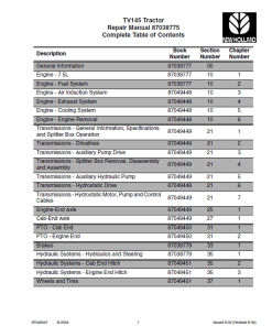 New Holland TV145 Tractor Service Manual
$37.00
 -
×
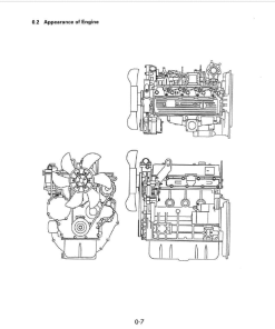 OM Pimespo 4D98E Diesel Engine For Forklift Trucks Shop Manual
$25.00
 -
×
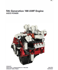 AGCO 5th Generation 168 AWF Engine Manual
$20.00
 -
×
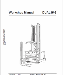 OM PIMESPO CTR Dual 10, Dual 13, Dual 15-3, Dual 15-4 Workshop Repair Manual
$28.00
 -
×
 New Holland TS6.110, TS6.120, TS6.125, TS6.140 Tractor Service Manual
$38.00
 -
×
 New Holland T4.55S, T4.65S, T4.75S Tractor Service Manual
$34.00
 -
×
 Liebherr LH80C, LH80M Tier 4F Hydraulic Excavator Service Manual
$35.00
 -
×
 New Holland TG210, TG230, TG255, TG285 Tractor Service Manual
$40.00
New Holland TT55, TT65, TT75 Tractor Service Manual
$34.00
Enhance your understanding with the New Holland Tractor Service Manual, featuring comprehensive guides for models TT55, TT65, and TT75.
Details:
- Pages: 767
- Brand: New Holland
- Type: Tractor
- Publication Number: 47899732 (June 2015)
- Language: English
- Format: PDF
Download this detailed manual to ensure optimal performance and maintenance for your New Holland tractors.
SKU: 186476
Categories: New Holland, Tractor
Service Manual: Table of Contents
Product Overview
This comprehensive service manual offers a detailed guide for the maintenance and repair of New Holland tractors. It emphasizes safety and precision, providing step-by-step instructions to ensure repairs are conducted with the utmost care and using the appropriate special equipment. Noncompliance with the guidelines may result in damage, for which the operator will be responsible.
Table of Contents
- Contents
- Introduction
- Engine
- Clutch
- Transmission
- Four Wheel Drive System
- Front Axle System
- Rear Axle System
- Power Take Off
- Brakes and Controls
- Hydraulic System
- Steering
- Wheels
- Electrical System
- Special Tool Index
Foreword
All maintenance and repair procedures described in this manual should be performed with extreme caution, adhering closely to the provided instructions. Specialized equipment, as recommended by New Holland, is crucial for reliable repairs. This equipment is custom-designed for New Holland tractors, ensuring efficient and durable performance.
Notes on Equipment
The equipment suggested within this manual is purposefully engineered for use with New Holland tractors. It is essential for ensuring reliable and accurate repairs and has been meticulously constructed and tested for longevity and efficiency.
Notice
Terms like u201cfrontu201d, u201crearu201d, u201cright-hand sideu201d, and u201cleft-hand sideu201d pertain to the tractor’s components as viewed from the operatoru2019s seat, oriented in the standard direction of movement.
Engine – Static Description
The manual details the engines available, including those with 4 cylinders (TT75) and 3 cylinders (TT55), as well as the naturally aspirated 3-cylinder with a turbocharger (TT65). These engines are designed with cross-flow cylinder heads, with intake and exhaust manifolds positioned on opposing sides. The combustion process is specially engineered to occur within the specially designed cavity in the pistons.
Cylinder Head Assembly
The cylinder head features valves and springs, and the valve rocker arm shaft assembly is secured to the cylinder block via the cylinder head. Retaining bolts are arranged in a six-point pattern around each cylinder to guarantee even pressure across the cylinder head. The right-hand side houses the intake manifold and diesel injectors outside the rocker cover, while the left side accommodates the exhaust manifold.
Only logged in customers who have purchased this product may leave a review.
Related products
$34.00
$36.00
$36.00
$34.00
$34.00
$36.00
$34.00
$36.00






Reviews
There are no reviews yet.