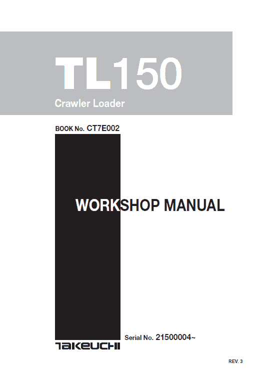
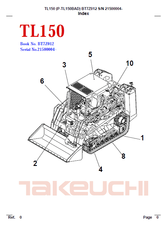
Takeuchi TL150 Compact Loader Service Manual
Product Overview
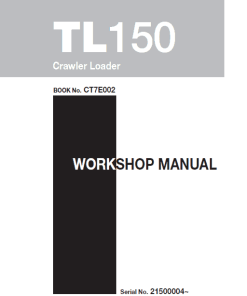
The Takeuchi TL150 Compact Loader Service Manual is an essential guide for the operation, maintenance, and repair of the TL150 model. This comprehensive manual is written in English and provides detailed instructions across several document formats.
This manual collection includes:
- Service Manual: 828 Pages
- Operating Manual: 196 Pages
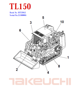
- Parts Manual: 573 Pages
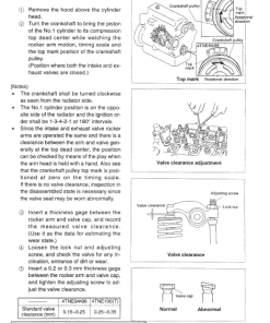
- Engine Manual for TL150 4TNE106T-TBL: 130 Pages
Applicable for all serial numbers, this manual is designed to support professionals involved in maintenance operations.
Key Features
- Comprehensive coverage of the loader’s operation, service, repair, and maintenance.
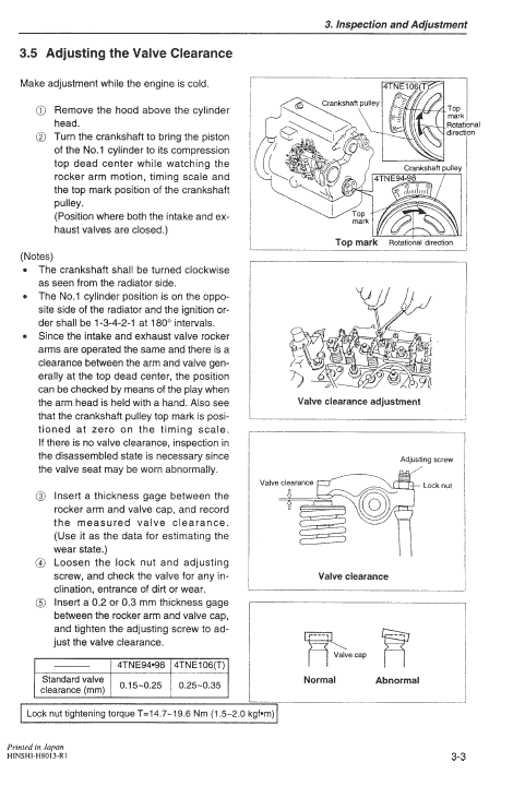
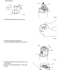
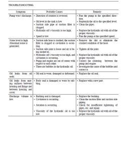
- Detailed breakdown of disassembly, reassembly, check procedures, and troubleshooting.
- Includes maintenance reference values and outline specifications.
- Contains safety instructions to ensure secure operation.
Benefits
- Enhances maintenance techniques through clear guidance and detailed diagrams.
- Facilitates troubleshooting and repairs by providing specific instructions.
- Keeps operational downtime minimal with quick reference guides.
- Ensures safety by adhering to prescribed operational standards.
Usage Recommendations
- Store the manual near or on the loader for easy reference during maintenance activities.
- Transfer the manual to new owners when selling the machine to preserve operational reliability.
- Conduct prescribed inspections before operation and address any issues promptly to prevent accidents.
Table of Contents Highlights
- General Information
- Specifications
- Machine Configuration
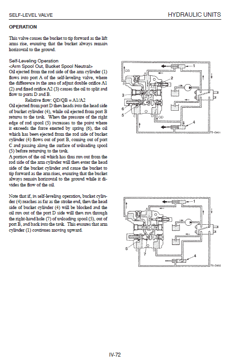
- Hydraulic Units
- Troubleshooting
- Engine Details
Note: The content and diagrams in this manual may vary due to design modifications. Always verify compatibility with your specific machine.
Extract from the Service Manual
Structural and Functional Outline
Turbine: The engine’s exhaust gas is accelerated in the turbine housing’s nozzle and directed onto the turbine impeller to rotate the shaft. The setup includes a seal ring and a heat insulating plate to protect bearings from exhaust gas impact.
Compressor: The compressor impeller, attached to the turbine shaft, rotates to draw in and compress air for the intake manifold, also known as the blower.
- Thrust Bearing: Prevents shaft movement due to constant thrust force.
- Radial Bearing: Features a floating design to ensure slow bearing sliding speed, enhancing dynamic stability.
Compressor Side Sealing Mechanism: A double wall structure with a seal ring and plate minimizes intake air and oil leakage.
Waste Gate: Regulates turbine rpm by bypassing excessive exhaust gas, maintaining specified intake pressure and optimizing response to load changes.
Only logged in customers who have purchased this product may leave a review.







Reviews
There are no reviews yet.